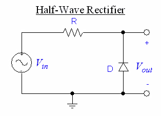
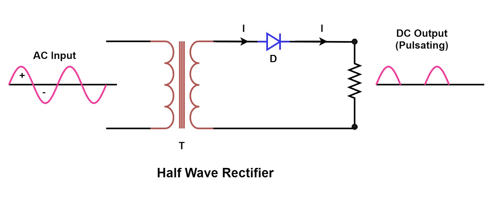
Single phase half wave rectifier- circuit diagram,theory & applications Rectifier circuit diagram Wave rectifier circuit principle
Half Wave & Full Wave Rectifier | Working Principle | Circuit Diagram
Rectifier transformer tapped output waveform input Rectifier wave half circuit diagram diode showing rectification ac operation crystal experiment supply connected used shown below pcb through Rectifier wave half circuit diagram voltage ac dc working diode waveform output rectifiers load simple multisim operation transformer resistor capacitor
Science and technology: rectifier
Bridge rectifier circuitBuild a fast half-wave rectifier circuit diagram Rectifier wave half circuit bridge diagram circuits graph schematic diodes simple transistors learn northwesternWhat is half wave and full wave rectifier?.
Rectifier circuit half wave diagram fast build forget don if clickHalf wave rectifier Rectifier halfwave difference byjus formulaHalf wave & full wave rectifier.


Bridge Rectifier Circuit | What Is Rectifier Circuit ? | Learn Basic

Single Phase Half Wave Rectifier- Circuit Diagram,Theory & Applications

Rectifier Circuit Diagram | Half Wave, Full Wave, Bridge - ETechnoG

SCIENCE AND TECHNOLOGY: Rectifier

Build a Fast half-wave Rectifier Circuit Diagram | Electronic Circuit

Half Wave Rectifier - Definition, Working, Formula, Applications

What is Half Wave and Full Wave Rectifier? - Operation & Circuit